Skip to main content area
Home
  • English
  • Español
  • Get it
  • Build it
  • Use it
  • Blog
  • DiyouPCB
    • Get It
    • Build
    • Use
    • Improve
    • Gallery
    • Downloads
  • Contact
  • About us

You are here

Home

TwinTeeth Launching

Submitted by DIYouware on Fri, 02/20/2015 - 14:34

We are continuously receiving emails from friends asking when we will publish the project.

We think next Monday (February, 23th) if all goes well (cross your fingers) you will see TwinTeeth.

Sorry because we are a bit delayed with respect to the plan but we didn’t stopped a second, just there was so much to do.

Last weeks we were: correcting small bugs on the software, redacting the web in English and Spanish, taking pictures of the robot, filming a video, mounting it, preparing the files with the blue-prints, circuits, software, etc.


Thank you very much for your interest.

Diyouware team.


  • Read more about TwinTeeth Launching
  • Log in or register to post comments

Lights, camera, action!

Submitted by DIYouware on Wed, 01/14/2015 - 19:40
 
It seems DiyouPCB MKI has appeared again in some blogs, just a year after publishing the project first time and its funny because we do not know why.

Last week we began receiving congratulations messages  so we searched "Diyouware" in google and we saw that we were present in important blogs like:  3ders.org, 3dPrint.com, Adafruit.com, Bricogeek.com, Imprimalia3D, Geeky-gadgets.com, etc.

Probably someone published the project in one of the blogs and then Internet spread it. Publicity and congratulations are always welcome, although it is about the old model. Anyway thanks very much for all!

Regarding our current project: “TwinTeeth - the PCB mini-factory”:
 
it runs according to the plan (that of course we change every day smiley) so in February we will publish it.
 
During the Christmas holidays we were very busy. We designed an inspection camera holder, we did more PCB printing testing and even had time to design and build a new FDM 3D printer since our Prusa Mendel is a little outdated.
 
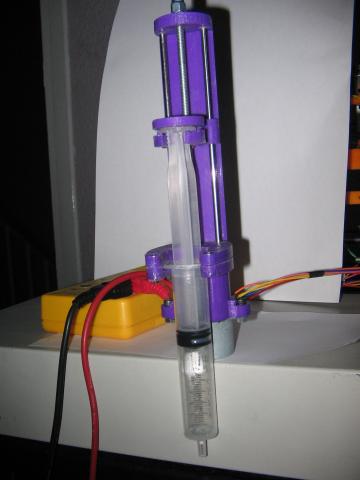
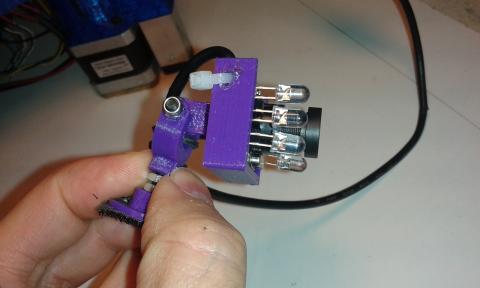
The camera is fundamental to print and manufacture high-density PCBs because sometimes we can not appreciate the details at a glance. It allows determining precisely the home position and the most important thing: setting it when we change the toolhead as there may be slight variations each time we manipulate the printer. It also allows us to inspect in detail the quality of the jobs and see how evolves them on the fly.
 
Here you can see a photo of the camera holder and the camera.

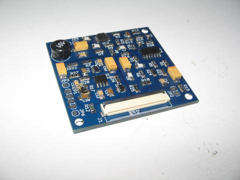
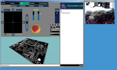
Below: the TwinTeeh’s Control Console. To the right, the live-video obtained with the camera.

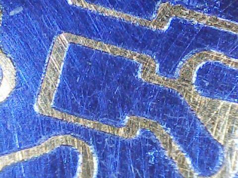
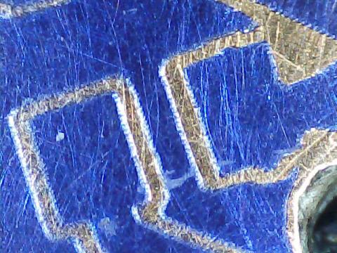
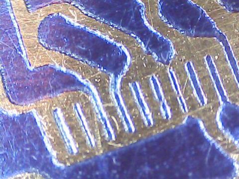
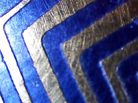
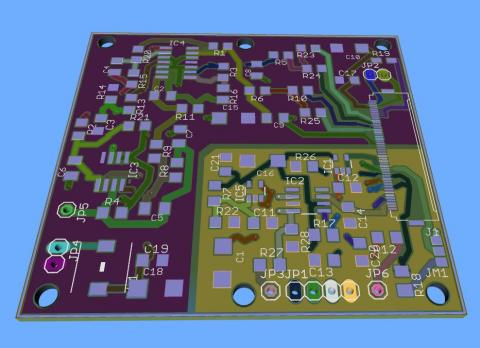
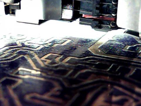
Next one a beatiful view of the PHR-803T lens coils above the PCB just printed.

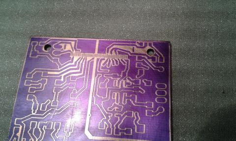
About printing testing:
 
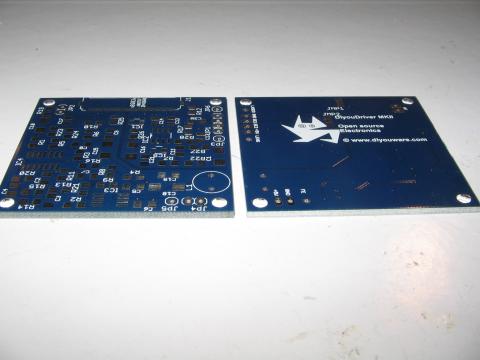
We had time to print some PCBs and every time we are obtaining better results and higher quality. At the same time we are discovering the best procedures to do it. We are already printing on two sides. This fixture bed helps us considerably to align them. It’s simple: we print the top PCB side, then turn it around and set it back on the fixture pins and then we print the bottom side. I remember how many hours I spent trying to align them in the almost complete darkness with traditional methods.
 
We are also changing some small details in the software. We want TwinTeeh to be very easy to use since we believe that any tool have to be user-friendly to be really useful.
 
Some photos:

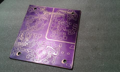
You can see in the picture above that the printing has been shifted a little to the left. This is because we set wrongly the home position. After this test we decided to implement the camera. Also we cut the PCB just to fit the circuit and it is not a good idea: it is better to make it a little bigger.

Regarding the Prusa I3:
 
We have made an "eclectic" version adopting the best of other printer models, especially from: BQ Hephestos, PowerCode, I3 Rework and of course the original Prusa I3 single frame.
 
We have also improved the printer's rigidity ans stability and reduced costs replacing the aluminum frame with one built with aluminium L-shaped profiles. It is something similar to plywood “box type” models but alu. version (plywood proably is not the best material to build a 3D printer since it absorbs moisture). We adopted a bowden type extruder and an E3D hot-end.
 
We named it Diyouware I3 and it is already printing. We will post all the part files and blue-prints in case someone wants to make it.


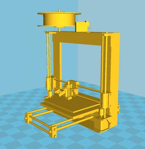
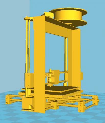
Just if someone has read the post very fast: this is NOT TwinTeeh, it’s only another Prusa I3 3D printer…smiley


  • Read more about Lights, camera, action!
  • 1 comment
  • Log in or register to post comments

Diyouware TwinTeeth: a PCB mini-factory

Submitted by DIYouware on Wed, 12/17/2014 - 10:30

Yes. We changed the name of the project to TwinTeeth. Why? Because we did not like MKII and also because that word inspired us in the robot designing. We don’t want to bore you now with the details so we will explain the full story when we will publish the project by january/february.

We have also coined a new term: PCB mini-factory. One year ago we had the vision of a robot which would help us to fabricate small PCB prototypes at home. During its development we though some possible definitions for this concept and now we think that mini-factory is the best.

More news: we tested the “professional-made” pickup’s driver PCB and the results are fantastic!!!

The electric noise has almost disappeared and we were able to focus with the IR diode very easily and without blurring the UV-film which was our primary goal. We were also able to turn on/off the red diode but we were a little afraid about destroying it, so in addition to the limiting resistor we also limited the diode intensity by firmware.

Take a look at some pics we took with a 20x microscope. They correspond to some details of the Pickup Driver PCB.

You can see on this one the 0.5mm pitch FPC connector tracks. It’s the small thing we have ever printed.

We will continue testing the printing quality but we can say that this stage has been almost surpassed.

Next stages: we have to 3D print some framework pieces we redesigned with improvements and then we will test the complete “mini-fabrication” process of a two-side PCB, including: designing, photoengraving, drilling, acid etching and dispensing solder paste on SMD pads. At the same time we will check usability and software functioning. We already tested the 3D printing toolhead but maybe we will also test it a little more. We would also like to test milling/carving on a soft material like expanded polystyrene or wax. For example it can be useful to make silicone moulds.

We hope the final functionality of the PCB mini-factory will be the following:

  • Laser photoengraving – consists in drawing the PCB circuit on sensitive film or board using a UV or IR laser.
  • Drilling – it allows drilling vias and holes using any mini-rotary tool like Dremel or Proxxon.
  • Milling/Carving/Etching – using the same tool, it can also mill or carve soft materials or etch PCB copper with a v-bit.
  • Solder paste dispensing – with a special syringe dispenser, it can deposit solder paste with precision on SMD PCBs pads.
  • Plotting – if you prefer this method, you can plot the circuit with a permanent pen-maker.
  • 3D printing – the mini-factory includes also a 3D printer so you can make knobs, boxes, front-panels, etc. with PLA or ABS. And also print circuits with conductive filament or graphene filament in the future!!
  • And much more… because it is extendable and you can use any other tool you can install on it.

All of this functionality is supported by the robot firmware and a new user-friendly management console we have been developing this year. It will help all of us to control the mini-factory and the different tools.

We also have detected some new possible applications:

  • UV resin 3D printing – we already talked about that. It is the well known Stereolithography (SLA) method. It consists in 3D printing objects with an UV laser in photo-sensible resin. We already drafted some blue-prints using the optical pickup and probably will be our next project.
  • Bio-polymer 3D printing – consists in 3D printing in  bio-polymers for tissue engineering. It seems easy: just add a UV photo-initiator to any hydro gel and 3D print on it with the UV laser beam. The benefit to use the pickup could be the precision because the laser beam is perfectly focused and close to the hydro gel surface. There are labs and universities around the world working on that.
  • Microscopic applications – we don’t have too much time to research more areas, but we dream with this kind of projects. It consists in using the pickup as a laser microscope or molecular tweezers.  In theory the laser beam is 0.5um wide so maybe is possible to do something at this scale.

Finally we promised to publish Dr. Futai’s document. Here it is:

http://www.digchip.com/datasheets/parts/datasheet/287/MLX75012.php

It is the datasheet of the photodiode array which we believe the pickup uses. This document confirms us the functionality of some of the pins we discovered last year and others we didn’t have any idea about it. It also allowed us to have a better control of the pickup’s laser diodes.

There is a lot of undiscovered pickup functionality yet. I hope our project had inspired some people to research more pins and end our job. For us it is enough as we covered our goals and we will continue with our real project: the PCB mini-factory.

Sounds good, isn't it?

  • Read more about Diyouware TwinTeeth: a PCB mini-factory
  • Log in or register to post comments

PCB Soldered

Submitted by DIYouware on Tue, 12/09/2014 - 10:07

PCB soldered

Last weekend we found time to solder the PCB. It was easy but we had difficulties to find a 60 ohms SMD resistor to limit Red/IR diode current. We searched in some e-waste circuits and finally we found one similar in an old TV but not SMD. Anyway we provisionally used it till we receive the good one.

We did not have time to test it, maybe next weekend.


  • Read more about PCB Soldered
  • 1 comment
  • Log in or register to post comments

PCB arrived

Submitted by DIYouware on Fri, 11/28/2014 - 11:22

The PCB samples we ordered have arrived today. They have a professional look. We will build one and test it as soon as possible.

We ordered some PCBs to a professional manufacturer because we wanted to test if the circuit still works while reducing traces, clearances, vias and sizing. Usually the quality of this kind of services is far away from the quality we can obtain at home, even with the robot. But as the circuit is so sensible to electric noise we wanted to know if it works better in a proffesional way.

This PCB is based on the latest driver circuit version....

  • Read more about PCB arrived
  • Log in or register to post comments

Good news

Submitted by DIYouware on Thu, 11/20/2014 - 10:12

We have very good news.

Last week Dr. Noboyuki Futai from Japan sent us a datasheet containing the last information we needed to reveal all the secrets of the PHR-803T. We will publish the document in the following days on the download page with the last version of the DiyouDriver’s schematics. This new version doesn’t use all the information provided by the document. We reviewed it and we think our electronics is enough for our current project, but the document solved all of our doubts, confirmed our researches and also will allow other people to exploit more capabilities of the pickup. From here we would like to express Dr. Futai our deep gratitude for his important contribution to the project.

On the other hand we are waiting for the arrival of some professional PCBs we ordered from a fab. These PCBs are smaller and more compact than those we made by ourselves but they take several weeks to come to our hands. As soon at they arrive we will test one to see if everything works fine and then we will publish the schematics and the document of Dr. Futai.

While waiting for the PCBs we are researching other areas.....

  • Read more about Good news
  • Log in or register to post comments

The Infrared Diode and the Paste Dispenser

Submitted by DIYouware on Tue, 11/11/2014 - 10:51

We were almost to throw in the towel trying to focus with the red diode when we did a quick test with the infrared one. We have a few pickups with the red diode burned but the infrared diodes seem still alive. When we discovered the way to turn on/off the blue and red pickup’s diodes we were also able to manage the infrared one (The infrared light is invisible to the human eye but you can see it through any video camera). But for some reason we didn’t see any wave in FE signal when trying to focus with it.

Reviewing old CD/DVD player’s manuals we saw that the photodiode is usually divided into two patterns: one for DVD and another for CD. That made us think that some pickup pin had to have the function of change from one photodiode pattern to the other. And so it was. There is a pin which allows switch from Blu-ray/DVD to CD mode. If not used, infrared diode turns on but no wave is obtained while focusing. We slightly modified the driver circuit and now we are able to focus with the infrared diode. The good news is that limiting the current with a resistor it seems it doesn't destroy itself. We still need to test a little more but it looks promising.

On the other hand, last week we designed and built the solder paste dispenser toolhead. The idea is that the robot also automates this task.

We used a small stepper motor, a linear axis, a small leadscrew and a syringe containing the solder paste. A few weeks ago we developed also the Eagle Cadsoft’s ULP program which generates the g-code file to move the robot and deposit the paste in the component's pads....

  • Read more about The Infrared Diode and the Paste Dispenser
  • Log in or register to post comments

Betting on red or black

Submitted by DIYouware on Thu, 10/30/2014 - 10:02

We made and tested the new laser circuit driver and the good news is that it works fine even better than MKI prototype. The isolation of the analog and digital circuits produces a free-of-noise FE signal which allow us to focus really better and which more accuracy than in previous versions. Analyzing the signal with the oscilloscope we saw that we don’t almost have any noise, only a small background RF noise probably generated by the environment.

The bad news is that unfortunally we could not focus with the red laser.

  • Read more about Betting on red or black
  • Log in or register to post comments

Noisy Neighbourhood

Submitted by DIYouware on Thu, 10/23/2014 - 12:39

We are still fighting with the electric noise. As we said in previous blog entries this problem affects the focus signal.

We are using the PHR-803T electronics and the astigmatic method to focus de laser on the PCB. To obtain the S-Curve we calc and amplify the A,B,C,D signals obtained from the pickup’s photodiode array and generate an analog signal (FE or Focus Error) which we read from an Arduino port. In a similar way DVD or Blu-Ray players focus the laser beam on the disc surface but using more complex circuitry because they have to do it in real time as the music or movie is playing. We only focus the laser beam once when begin to print the PCB so our circuit is more simple.

We developed all this method and electronics last year and were working fine in MKI, but in MKII we did the mistake to mix the digital and analog circuitry on the same PCB, so the digital circuitry induce noise on the sensible analog signals and eclipsed the S-Curve.

We think the solution will be to isolated digital and analog circuits on different PCB areas and use different GND and VCC lines connected in a star configuration to a common point. Also to reduce PWM traces length ad minimum, isolate connector pins and decouple everything with some tantalum capacitors which are more suitable to the range of frequencies we are treating. We also included a choke to see if it filter well the power suply noisy frecuencies.

So we redesigned the circuit and the board and here it is: (courtesy of ZofzPCB 3D Gerber viewer)


The smaller area is the digital circuit: the noisy neighbourhood.

  • Read more about Noisy Neighbourhood
  • Log in or register to post comments

Red laser issues and Eagle User Language Program

Submitted by DIYouware on Fri, 10/10/2014 - 21:53

We are still testing the focus system with the red laser.

It was easy to turn the laser on but unfortunally the red diode needs less current than the blue and when we turn it on it auto-destroyed. It happend three times till we deducted the problem, so we killed three pickups during this testing. Now that we know the problem we are limiting the current of the red laser diode and.....

  • Read more about Red laser issues and Eagle User Language Program
  • Log in or register to post comments

Pages

  • « first
  • ‹ previous
  • 1
  • 2
  • 3
  • 4
  • 5
  • next ›
  • last »

(c) 2013 Diyouware.com