Skip to main content area
Home
  • English
  • Español
  • Get it
  • Build it
  • Use it
  • Blog
  • DiyouPCB
    • Get It
    • Build
    • Use
    • Improve
    • Gallery
    • Downloads
  • Contact
  • About us

Plataforma de fijación multi-capa

Submitted by DIYouware on Wed, 07/09/2014 - 22:08

Algunos días atras describimos cómo habíamos diseñado la plataforma de fijación para que cumpliera todos los requisitos. Pues bien, hemos construido todos los componentes para probar si el sistema funciona y finalmente tiene este aspecto:


En la foto se pueden observar las diferentes capas de la solución:


  • Read more about Plataforma de fijación multi-capa
  • Log in or register to post comments

Multi-layer fixture system

Submitted by DIYouware on Wed, 07/09/2014 - 22:05

Some days ago we described how we designed the bed to fulfil all the requirements. In this way we built all the components of the bed in order to test if the complete system works with the different tools and finally it looks like this:


You can see in the picture the different removable layers:


  • Read more about Multi-layer fixture system
  • Log in or register to post comments

Mas pruebas y nuevo conector de herramientas

Submitted by DIYouware on Thu, 07/03/2014 - 19:57


Continuamos con las pruebas de la impresora imprimiendo en modo raster.

Cada vez obtenemos mejores resultados.

También hemos diseñado una carcasa para alojar el conector para las herramientas.


Estamos usando 15 hilos y un conector DB15 para transmitir todas las señales y líneas de corriente que pueda necesitar cualquier posible herramienta. La idea aquí es que cualquier adaptadador de herramienta pueda utilizar este conector con una configuración de pines estándar para conectarse a la impresora. De esta forma sustituir una herramienta por otra será mucho más fácil.


  • Read more about Mas pruebas y nuevo conector de herramientas
  • Log in or register to post comments

More testing and toolhead connector

Submitted by DIYouware on Thu, 07/03/2014 - 19:51


We continue with the printer testing in rastering mode.

Every time we obtain better results.

We also designed a bus connector case.


We are using a 15 wire cable and a DB15 connector for carry all the signal and power lines that any tool might need. The idea is that every toolhead will use that DB15 connector with a standard pinout. In this way,  It will be easy toolhead substitution.


  • Read more about More testing and toolhead connector
  • Log in or register to post comments

DiyouPCB MKII: Preliminary Specifications

Submitted by DIYouware on Tue, 06/24/2014 - 17:37

The following is a list of preliminary specifications for the new robot:

Working area

70x80x80mm (X,Y,Z). We reduced it considerably to an Arduino Shield size. In fact sometimes we call the robot “The Arduino Shield Maker”. We reduced it because we preferred to do something small but precise. Rarely all of we create big circuit boards but if you need it you can always split the circuit in two or more modules. Reducing the working area has some advantages: the robot is cheaper, more precise, robust, smaller and more manageable.

Motion

MKII is powered by three Nema 17 motors and Acme screws. We substituted the timing belts we used in MKI in order to eliminate vibration and resonances. It was mainly the solution and now the laser draws on the PCB with a stable beam without any mechanic disturbance.

Speed

We can go as fast as 1200-1500mm/min. We think it’s enough for our purposes. The Acme screw pitch set the limits. The robot can go faster upgrading the screws to ones with more pitch but at a price.

  • Read more about DiyouPCB MKII: Preliminary Specifications
  • Log in or register to post comments

DiyouPCB MKII: Especificaciones preliminares

Submitted by DIYouware on Tue, 06/24/2014 - 17:35

La siguiente es una lista de las especificaciones preliminares del nuevo robot:

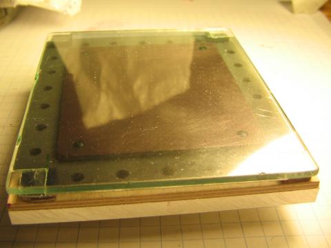
Área de trabajo (X, Y, Z)

70x80x80mm. La hemos reducido considerablemente a un tamaño de Shield Arduino. De hecho a veces llamamos al robot "The Arduino Shield maker". La hemos reducido porque preferíamos que fuese antes precisa que grande. Raramente creamos en casa PCBs de gran tamaño, pero si lo necesitáramos, siempre podemos dividir el circuito en dos o más módulos e imprimirlos por separado. Reducir el área de trabajo tiene algunas ventajas: el robot es más barato, más preciso, robusto, más pequeño y más manejable.

Mecánica

MKII es impulsado por tres motores Nema 17 y husillos trapezoidales. Sustituimos las correas dentadas que usamos en la MKI por husillos para eliminar los problemas de vibraciones y resonancias. Después de las primeras pruebas hemos visto que efectivamente es la solución y ahora el láser dibuja con un rayo preciso y estable sin ninguna perturbación mecánica.


Velocidad

Podemos ir tan rápido como 1.200-1.500mm/min. Creemos que es suficiente para nuestros propósitos. El paso (pitch) de los husillos establece el límite de velocidad. El robot puede ir más rápido actualizando los husillos a un paso más elevado pero aumentando considerablemente el precio.

  • Read more about DiyouPCB MKII: Especificaciones preliminares
  • Log in or register to post comments

Nueva plataforma de fijación

Submitted by DIYouware on Thu, 06/19/2014 - 14:29

Hoy hemos recibido la plataforma de fijación de aluminio que ha mecanizado un amigo mío y es fantástica


Una de las cosas que hemos aprendido en el desarrollo de la MKII es lo importante que es fijar bien la PCB a la plataforma de impresión.

Hemos intentado diferentes soluciones......

  • Read more about Nueva plataforma de fijación
  • Log in or register to post comments

New aluminium fixture plate

Submitted by DIYouware on Thu, 06/19/2014 - 14:06

Today we received the aluminium fixture plate a friend of mine made. It's fantastic.


One of the things we have learned on the development of MKII is how important is to fix well the PCB to the printing bed.

We tried different solutions:.....

  • Read more about New aluminium fixture plate
  • Log in or register to post comments

Pruebas de Impresión

Submitted by DIYouware on Tue, 06/17/2014 - 21:52

Hoy hemos realizado más pruebas de impresión en modo rastering con resultados muy buenos.

El proceso de imprimir en modo raster comienza en Eagle CadSoft. Allí tenemos que exportar la PCB a formato Postcript (Device: PS en el procesador CAM de  Eagle). Una vez exportada sólo tenemos que abrirla con la nueva herramienta de gestión del robot (DiyouRun V2.0) y enviársela.

DiyouRun a cambiado mucho desde la última versión y ahora tiene un nuevo aspecto adaptado al nuevo robot.

  • Read more about Pruebas de Impresión
  • Log in or register to post comments

Printing test

Submitted by DIYouware on Tue, 06/17/2014 - 21:29

Today we continue with the printing tests in rastering mode with very good results.

The process of printing in raster mode begins on Eagle CADSoft which is the tool we use to design the PCBs.

Once the board is finished then we export it to PostScript format (Device: PS in the Eagle’s CAM processor) and open it with DiyouRun V2.0.

DiyouRun has change a lot since last version and now it has a new look and feel adapted to the new robot.

  • Read more about Printing test
  • Log in or register to post comments

Pages

  • « first
  • ‹ previous
  • …
  • 10
  • 11
  • 12
  • 13
  • 14
  • 15
  • 16
  • 17
  • 18
  • next ›
  • last »

(c) 2013 Diyouware.com