Last week we had time to continue researching about making vias with conductive ink.
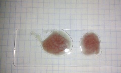
We tried to fill the vias with the copper nano-particles ink but we brewed a very slippery one. It drains so easy through the holes that was difficult to fill the vias. We though add some viscous agent to the ink, but finally we had a brilliant idea.
Really we don’t need holes to make vias. Well, we need holes, but not through-holes. I mean, we can avoid drilling to bottom copper layer and make blind-vias like tiny wells instead of vias!
The idea is to drill holes taking care not to drill the bottom copper sheet. Then fill the tiny wells from inside, inserting a needle and injecting the conductive ink, mainly because it will be difficult to fill it from outside due to the air inside the well and also surface tension forces.
Both are simple tasks for a robot.
How to drill PCB wells
If we want to make PCB wells we need to detect in some way when the drill-bit tip touches the bottom copper layer. Then withdraw it quickly before it could damage the copper sheet.
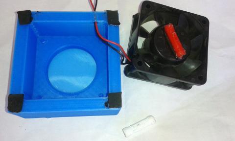
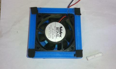
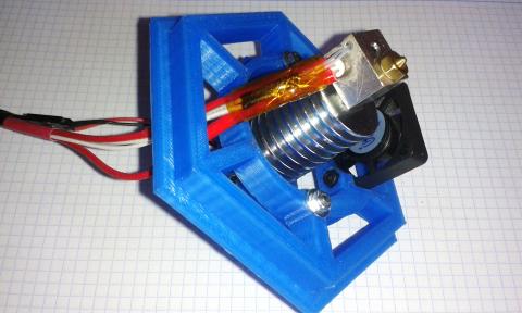
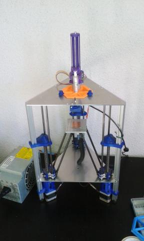
In order to do it, we designed a “drilling interruptus device”. It is made with a carbon brush. We used a standard DC motor carbon brush and some bolts&nuts to attach it to the Dremel Toolhead.
The brush is always in contact with the drill collar and connects the drill bit to the electronics while the shaft is rotating. We used TwinTeeth’s auto-levelling probe circuit to detect when the tip touches the copper.
We also connected the bottom side of the PCB to the electronics through the spring cable, which is the other pole of the circuit, and we wrote a firmware modification which detects the event and manage the situation.
When the bit tip touches the bottom copper layer, the bot quickly withdraws the drill (really it withdraws the PCB because TwinTeeth moves the bed instead the tool).
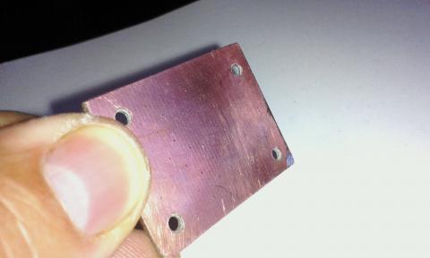
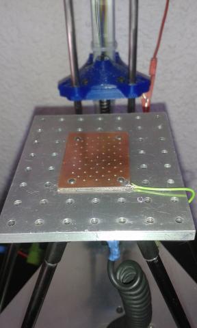
The result is tiny wells instead of holes. They have an entry on the top copper sheet and a little bump on the bottom sheet produced by the bit tip.
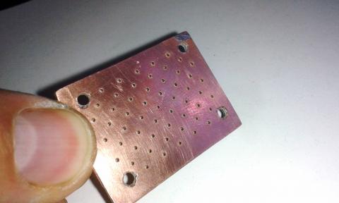
Picture above shows the top side.
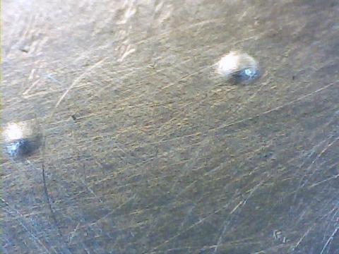
And above is the picture of the bottom side with the bumps.
These bumps were unexpected but really useful because probably they will fill up with conductive ink and help create electric contact with the bottom layer.
Filling the wells with conductive ink
Ok, we were clever finding a way to drill the tiny wells but fill them won’t be so easy.
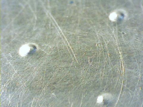
We took some pictures of the wells and its mouths at the microscope. They look like these:
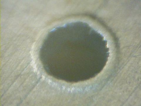
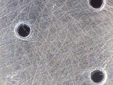
Not nice, they seem black holes of 0.75-0.8mm of diameter because we used a 0.7mm drill bit.
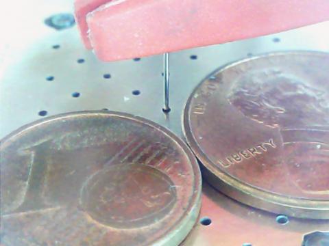
Next step is threading there the dispenser needle and inject the ink with a syringe.
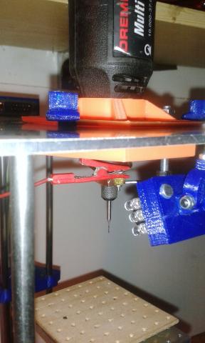
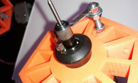
You can see the needle into a well on next picture. We included one-cent coins to show you the size of the tiny wells. In red, the crocodile clip which connects the needle to the Arduino detecting when it touches the copper.
TwinTeeth's Dispenser Toolhead uses a 10cc syringe, may be it is too big for the task. Instead we should use a micropipette because we only have to dispense 0.854mm3 into each via, we thought.
We made the micropipette using a 2mm ID teflon tube and a 27-gauge needle (0.21 ID, 0.41mm OD). We installed it inside the 10cc syringe to fit it on the Dispenser Toolhead.
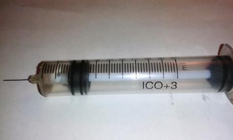
But it did not work very well because the plunge leaks. So finally we decided to use a 5ml standard syringe and we also installed it inside the 10cc syringe. What a mess of sryinges...

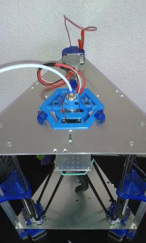
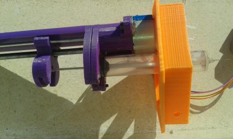
The idea is to fill the syringe with some ml of conductive ink. Then install the syringe on the dispenser and let the bot make the hard work.
It has to move to each via position and carefully insert the needle on each well. Then stops when it reaches the specified depth, or the needle touches the bottom copper sheet. Finally, it has to inject the ink on the well and run away to the next one.
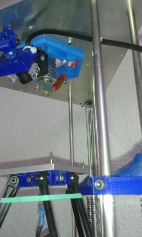
We also implemented an algorithm which quickly withdraws the platform in case the needle tip touches the top copper sheet. This is to avoid breaking the needle but also to have the opportunity to try again displacing a little bit the shot position. You can see on the last picture a green wire which connects the top layer to the spring wire which allows this function.
So we connected the syringe and the PCB top layer to the electronics and modified the firmware to implement this behaviour.
The software chain
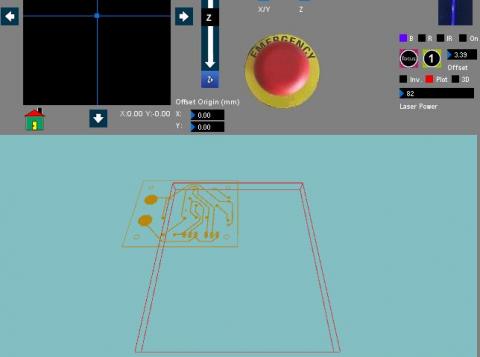
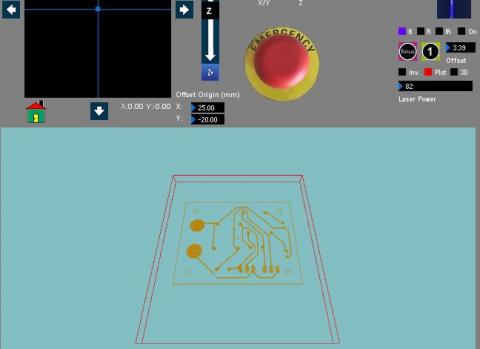
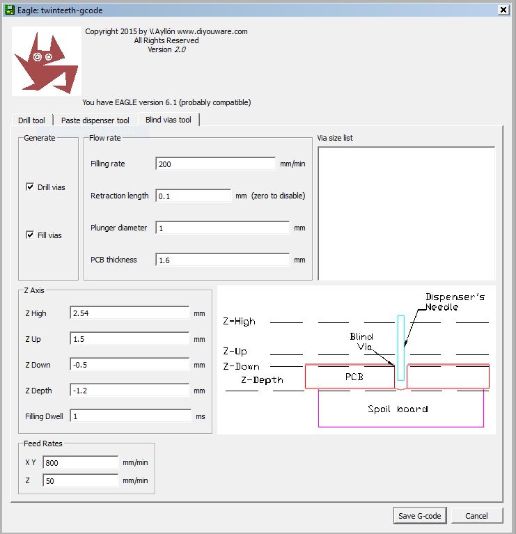
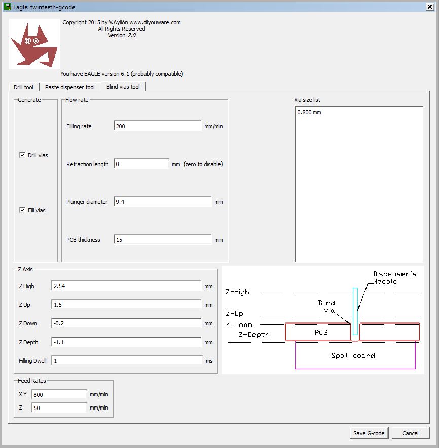
The process begins on Eagle Cadsoft.
We wrote a new Eagle’s ULP (User Language Program). It allows configuring the drilling/filling process and adjusting the various parameters. This program reads the vias information present at the board and generates the g-code needed to control TwinTeeth.
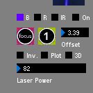
Then we used TwinTeethMC to load the g-code and control the robot.
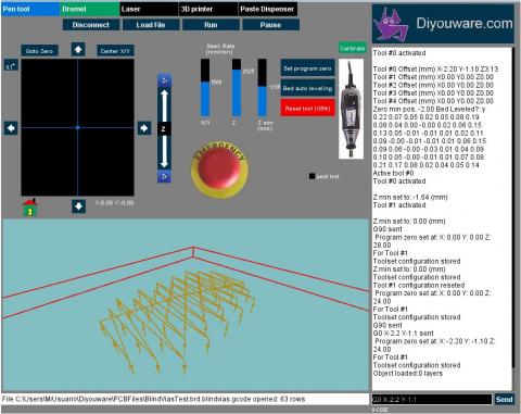
Finally we modified the bot firmware to implement the new behaviour, as we said.
Additional features
We think we will be able also to implement a process for testing the vias using the bot.
It could use the auto-levelling probe to check vias conductivity and mark on the console those vias which does not work and those which does. It could also meter automatically the vias resistance and provides a complete quality control system.
Results
It works! And the method seems feasible saving a lot of time. No more melancholy making vias...:-)
We made a proof of concept without ink (we only have a few) and filmed a video. It’s very interesting see how TwinTeeth makes the work with so precision. You will see that sometimes, while threading the needle it fails, but recovers the situation using the algorithm we implemented and retry again.
Next time we will try using the conductive ink. We still need to improve the ink formulations and find a cheap source or copper nano-particles, although we could also use any commercial silver ink which probably works better, but at a cost.
Anyway, a selective dispensing method of silver conductive ink has a lot of advantages from the cost point of view, because we don't waste a drop of ink.
Reading some papers we took note of some additives for make good conductive inks. Some of them uses PEG, PVP, PVA even gum arabic. We have to test them. PEG is a surfactant which decreases the surface tension forces. It is used in paper inkjet printers as an ink solvent. PVP is used to avoid particles form lumps.
Summarizing
This is a small step in the process of improving making PCB vias at home. We hope have contributed a little to it. Also we hope have inspired other people to researching in this way. We will continue to do it, and also researching about what we think will be the definitive DIY solution: 3D printing electronics.
Stay tuned!