Skip to main content area
Home
  • English
  • Español
  • Get it
  • Build it
  • Use it
  • Blog
  • DiyouPCB
    • Get It
    • Build
    • Use
    • Improve
    • Gallery
    • Downloads
  • Contact
  • About us

TwinTeeth Plus - Preparing the materials


Bill of materials

You will need the following materials to build the framework:

English
  • Read more about TwinTeeth Plus - Preparing the materials

Resumen de Septiembre

Submitted by DIYouware on Sun, 10/04/2015 - 17:45

No encontrábamos un momento para escribir nuevas entradas en el blog, pero ayer John Ferguson del Reino Unido nos ha enviado algunos archivos .STL con mejoras en las piezas de plástico de TwinTeeth y decidimos sentarnos, escribir estas líneas, publicar aquí sus archivos y por supuesto dar las gracias a John por su excelente trabajo y por su contribución al proyecto.

En septiembre hemos estado muy ocupados preparando y vendiendo los kits de la tienda. Después de las vacaciones de verano teníamos algunos pedidos pendientes y los hemos servido todos durante septiembre.

Hemos cambiado un poco la configuración de los kits. Ahora estamos utilizando plástico de color azul claro en vez del azul marino que estábamos usando antes del verano. Este color tiene una gran demanda en el mercado y ocurre que con frecuencia nos resulta difícil encontrarlo porque se encuentra agotado. Así que hemos cambiado a azul claro que es más fácil de encontrar. También hemos incluido por defecto el kit de la plataforma de aluminio en el kit del Hardware del Bastidor ya que nuestro proveedor tubo tiempo durante el verano para hacer algunos juegos y ahora tenemos cierto stock. Esperamos que podamos controlar la demanda. También encontramos tiempo para mejorar el sistema de movimiento lineal y los kits incluyen ahora los nuevos husillos y sus soportes (ver entrada en el blog).

Por otro lado hemos abandonado el proyecto de hacer un Toolhead para imprimir en SLA. Hemos probado con éxito el PHR-803T y su controlador para curar resina UV, pero no hemos visto ninguna ventaja de utilizar un robot delta invertido para ello. Probablemente un robot cartesiano tradicional hará un trabajo mejor, pero comenzar un nuevo diseño en esta área nos desviaría de nuestro objetivo. Por ello hemos cambiado el foco de nuestras actividades de investigación a otra área importante: cómo mejorar la forma de soldar vías. Nos gustaría hacer algunas pruebas con TwinTeeth y usarla para soldar y testar vías porque son siempre una pesadilla al hacer PCBs en casa. Tenemos algunas ideas absurdas, que como siempre parecen ser las mejores. Si la idea no es lo suficientemente absurda entonces alguien probablemente la habría hecho ya. Y en esta etapa de desarrollo tecnológico sólo tenemos dos oportunidades: la investigación en áreas complejas y difíciles que requieren invertir mucho tiempo y dinero, o encontrar una puerta trasera: algo que nadie pensaba porque era absurdo. Como podéis imaginar la segunda forma es nuestra especialidad y aquí estamos: pensando en nuevos métodos para soldar vías utilizando un robot. Todavía estamos esperando algunas cosas que hemos comprado en eBay pero os mantendremos informados de los resultados tan pronto como sea posible.

También estamos estudiando óptica porque queremos hacer alguna investigación sobre cómo sensibilizar dry-film con galvos, espejos poligonales, lentes, dispositivos LCoS y LCD y en general cualquier otro método óptico, en lugar de mecánico. Cuando descubrimos el PHR-803T nos enamoramos de él y de su sistema optomecatrónico. La óptica es una importante área de la mecatrónica y no sabemos demasiado sobre ella, así que vamos a tratar todos los días en aprender un poco sobre "el oscuro mundo de la luz...” o sobre “el lado oscuro de la fuerza " que es algo parecido :-)

También nos gustaría probar TwinTeeth para pintar circuitos impresos utilizando grafeno. Hemos encontrado algunas experiencias en internet donde transforman el óxido de grafito en grafeno mediante un rayo láser. Maher El-Kad de la Universidad de UCLA lo hizo por primera vez con LightScribe: una tecnología algo obsoleta que utilizaba un láser de DVD para pintar la portada del disco en la capa superior del DVD. El método que utilizó Maher para hacer el grafeno parece simple: cubrió un sustrato de plástico con una solución acuosa de óxido de grafito, la dejó secar y finalmente utilizó el rayo láser de LightScribe para transformar el óxido de grafito en grafeno.

Podéis encontrar más información aquí y algunos videos en youtube como éste.

El primer problema que hemos encontramos en este proyecto ha sido el precio del óxido de grafito. Aunque sabíamos que no era tan caro como el grafeno, que es realmente caro, hemos visto que tampoco es que sea muy barato: aprox. 180$ por gramo. De hecho es más caro que la tinta de las impresoras de inyección: el líquido más caro del mundo. :-)

También tuvimos tiempo para colaborar con Mecaduino. Conocimos a la gente de Mecaduino el pasado mes de mayo en la Maker Faire. Amablemente se ofrecieron a enseñarnos cómo utilizar sus piezas de metal en nuestros diseños y ahora estamos hablando con ellos para hacer un proyecto juntos.


Eso es todo!

Os mantendremos informados.

  • Read more about Resumen de Septiembre
  • Log in or register to post comments

September summary

Submitted by DIYouware on Sun, 10/04/2015 - 13:52

We did not find a moment to write new blog entries, but yesterday John Ferguson from the UK sent us some .STL files with improvements on the TwinTeeth plastic parts and we decided to sit down, write these lines, publish here the files and thank John for his excellent work and for his contribution to the project.

During September we have been really busy with the shop and making kits. After the summer vacation we had a lot of pending orders and we served them during September. 

We changed a little the kit configuration we are selling. We are using now a blue-light colour for the plastic instead the navy-blue which we were using before the summer. This colour has a big demand on the 3D printing market and frequently occurs that it is difficult to find because it’s sold-out. We changed to light-blue which is easy to find. We also included by default the aluminum platform kit in the Framework Hardware Kit because our provider had time during the summer to make some kits and now we have stock. We hope to control the demand. We also found time to improve the linear motion system and the kits include now the new lead-screws and supports (see blog entry).

On the other hand we abandoned the project of making a SLA Toolhead. We successfully tested the PHR-803T pickup and the driver to cure UV resin, but we did not see any advantage using an inverted delta robot. Probably a traditional cartesian robot will do a better job but beginning a new design would divert us from our goal, so we changed the focus of our researching activities to another side: improving the way of soldering vias. We would like to do some testing with TwinTeeth and use it for soldering and testing vias because they are always a nightmare when making PCBs at home. We have got some absurd ideas. Once again they seem the best. If the idea is not absurd enough then somebody has probably done it already. At this stage of technological development we only have two opportunities: research on complex and difficult areas investing a lot of time and money or find a backdoor: something that nobody thought of because it was absurd. As you can imagine the second way is our specialty and here we are: thinking about new methods to soldering vias using a robot. We are still waiting some equipment we bought and will keep you informed as soon as possible about results.

We are also studying optics because we want to do some researching about how to sensitize dry-film using galvos, polygonal mirrors, lenses, LCoS and LCD devices and in general any other optical method rather than mechanical. When we discovered the PHR-803T we fall in love with it and with its optomechatronic system. Optics is an important area of mechatronic and we don't know too much about it, so we will try everyday to learn a little about “the dark world of the light"…I mean: "the dark side of the force” :-)

We also would like to test TwinTeeth for printing circuits using graphene. We found some experiences on the internet where people are transforming graphite oxide in graphene using a laser beam. Maher El-Kad from UCLA University did it for the first time using LightScribe. This is an old technology which uses a DVD laser to burn a cover image into the top layer of the DVD. The method he used to make graphene seems simple: he covered a plastic substrate with a graphite oxide aqueous solution, let it dry and finally he used the laser beam to transform the graphite oxide into graphene.

You can find more information here and some videos on youtube like this one.

The first problem we found in this project was the graphite oxide’s price. We though it was cheaper than graphene which actually is really expensive. But graphite oxide is not cheaper: approx. 180$ per gram. In fact it is more expensive than inkjet printer ink: the most expensive liquid in the world.

We also had time for collaborating with Mecaduino. We met Mecaduino guys last May at the Maker Faire. They gently offered to teach us how to use more metal parts in our designs and now we are talking about how to make a project together.

That's all!

We will keep you informed.

  • Read more about September summary
  • Log in or register to post comments

Control IP5 2.2.5

Submitted by DIYouware on Wed, 09/16/2015 - 10:14

El equipo de desarrollo de ControlP5 ha desarrollado una nueva versión (2.2.5) que tiene algunos cambios no soportados por TwinTeethMC.

Estamos trabajando para adaptar TwinTeethMC a dichos cambios. Mientras tanto debéis usar la versión soportada, que es la 2.0.4.

Podéis descargarla desde aquí.


Gracias,

Diyouware team.


  • Read more about Control IP5 2.2.5
  • Log in or register to post comments

Control IP5 2.2.5

Submitted by DIYouware on Wed, 09/16/2015 - 10:10

Control IP5 library guys have released a new version (2.2.5) which has several changes not supported by TwinTeethMC.

We are adapting our tool to these changes. Meanwhile please download and install version  2.0.4 which is supported.

You can download it from here.

Sorry for any incovenience.

Diyouware team.


  • Read more about Control IP5 2.2.5
  • Log in or register to post comments

Mejoras en los husillos

Submitted by DIYouware on Tue, 09/01/2015 - 15:53

Después de algunos días de vacaciones hemos regresado revitalizados y con ideas frescas.

Una de ellas ha sido mejorar la precisión mecánica de TwinTeeth. Los valores actuales están bastabte bien pero durante las pruebas de impresión 3D usando resina UV vimos que algunas líneas rectas aparecían un poco torcidas a escala de micrometros.

Probablemente la razón es que algún husillo tiene algo de excentricidad o tal vez los acopladores de los motores son demasiado flexibles o ambas cosas. Así que hemos repasado el diseño del sistema mecánico para minimizar este efecto y finalmente decidimos reducir el tamaño de los husillos para reducir el posible giro excéntrico y también hemos diseñado un nuevo soporte superior del husillo que llevará el cojinete y un tornillo para ajustar la flexibilidad del acoplamiento motor.

Realmente TwinTeeth no necesita unos husillos tan largos porque no se utiliza la parte superior de ellos. Los carros viajan sólo unos 140-150mm desde la posición de inicio y por lo tanto podemos reducir la longitud del husillo y reducir de esa forma la probabilidad de que se tambalee mientras gira. Hemos pensado también reducir el tamaño de las guías lineales pero añaden rigidez al bastidor y sinceramente no vemos beneficio alguno.

Estas modificaciones son fáciles de aplicar y se pueden reutilizar los materiales importantes: husillos y rodamientos. Tendrás que comprar sólo algunos tornillos y tuercas e imprimir en 3D dos nuevas piezas: el soporte superior del husillo y su cubierta. Caben en el tamaño de la cama de TwinTeeth así que si tienes el Cabezal de Impresión 3D probablemente puedes imprimirlos con ella (antes de desmontarla). De lo contrario podemos proporcionarte un kit con las piezas. Los nuevos kits del bastidor incluirán también estas modificaciones.

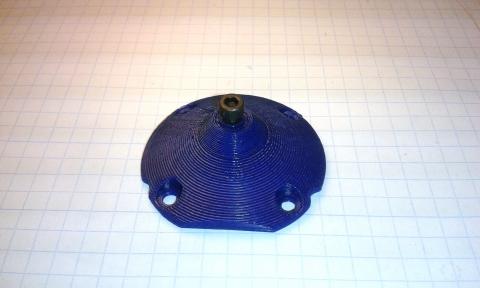
Este es el aspecto de las nuevas piezas:

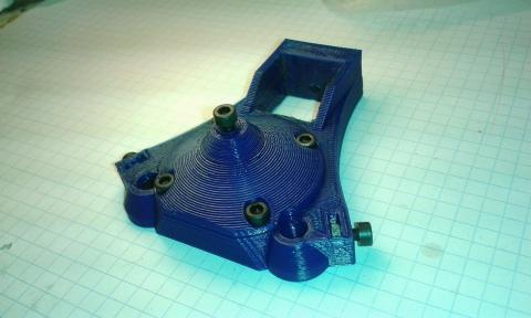
Y este una vez ensambladas:

La lista de materiales necesarios por cada eje es la siguiente:

  • 1x lead-screw top support  (soporte superior del husillo)
  • 1x lead-screw top support cover (cubierta del soporte)
  • 6 x tornillos/tuercas M3 -10mm
  • 1x tornillo/tuerca M3 -12mm
  • 1x tornillo/tuerca M4 - 30mm
  • Un poco de cinta de Teflon
  • Vaselina o grasa

Necesitarás además las siguientes herramientas.

  • Llaves allen M2, M3
  • Un destornillador pequeño
  • Una sierra de metal
  • Una lima
  • Un rotulador

¿Cómo hacerlo?

Primero tienes que obtener (o imprimir en 3D) las nuevas piezas de plástico. Luego quitarles los restos de la impresión, pie de elefante, hilos, etc.

Mediante el soldador inserta las tuercas M3 en sus alojamientos e instala los tornillos M3x10mm de retén del los ejes lineales. No olvides el tornillo M3x12mm de ajuste del husillo que está en la parte superior de la cubierta.

Luego desmonta el triángulo superior. Retira los tres rodamientos de bolas F6900ZZ e instálalos en las nuevas piezas. Utiliza algo de cinta de teflón para que encajen en sus alojamientos.

Pon un poco de vaselina o grasa en la punta del tornillo de ajuste (M3x12mm). Reducirá la fricción con el husillo.

Utilizando cuatro tornillos M3x10mm, atornilla la tapa en la parte superior del soporte de husillo. Esta tapa evita que el rodamiento salga de su alojamiento.

Afloja los tornillos y retira la tuercas de epoxy de los carros. Afloja también los prisioneros del acoplador del motor y retira los tres husillos deslizándolos hacía arriba.

Usando una sierra de metal corta los husillos a 200mm de longitud y redondea los extremos con una lima.

Por cada eje:

Toma uno de los soportes superiores de husillo. Comprueba que los pernos de retención están aflojados. Desliza hacia abajo la pieza por las guías lineales y el tubo de aluminio hasta que se encuentre aprox. a 147mm de la superficie del triángulo inferior (medido desde la parte superior de este).

Con un rotulador, marca la posición del tornillo M4 en el tubo de aluminio. Desliza hacía arriba el soporte del husillo y con una broca de 3 o 3,5 mm, taladra un agujero a través del tubo. ADVERTENCIA: ten cuidado al taladrar el tubo de eje Z porque probablemente ya instalaste el cableado dentro.

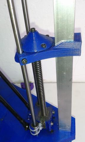
Afloja los tornillos del acoplador del motor. Instala provisionalmente el husillo enroscándolo a través de la tuerca del carro y deslizándolo por el rodamiento del triángulo inferior  hasta que alcance el acoplador del motor. Luego desliza el nuevo soporte superior por el tubo de aluminio y las guías hasta su posición y atorníllalo al tubo con un tornillo M4. Aprieta también los retenes de las guías lineales.

Gira el husillo a mano e insértalo en la parte superior del cojinete hasta que toque el tornillo de ajuste. Entonces usando un pequeño destornillador apalanca hacía arriba el acoplador del motor hasta que quede comprimido contra el extremo inferior del husillo. Entonces aprieta los prisioneros para mantener el acoplador del motor en esa posición. La idea es eliminar la flexibilidad del acoplador y el movimiento vertical del husillo. Más adelante podrás ajustarlo si fuese necesario, girando el tornillo de ajuste del soporte superior.

Utilizando un rotulador marca la posición de los rodamientos superior e inferior en el husillo. Luego, afloja los prisioneros del acoplador (sólo los que retienen el husillo), desmonta todo el conjunto y retira el husillo. Aplica un poco de cinta de Teflon en las marcas que hiciste con el objeto de reducir la holgura con los rodamientos.

Instala de nuevo el husillo y comprueba que ajusta bien en los rodamientos. Es muy importante que el husillo se adapte perfectamente a ellos para evitar cualquier bamboleo. Luego instala de nuevo la parte superior del soporte del husillo. Esta vez tendrás que hacer presión contra el husillo para comprimir el acoplador del motor. Instala entonces el tornillo M4 y aprieta los retenedores de los ejes lineales.

Coloca entonces la media tuerca de epoxi en el carro y aprieta los tornillos.

Comprueba con los dedos que el husillo gira suavemente. Muévelo también arriba y abajo y comprueba que no hay desplazamientos verticales. Lo ideal es que no se desplace verticalmente, pero si ves que va muy forzado o se bloquea, afloja un poco el tornillo de ajuste de la tapadera.

Finalmente comprueba que los prisioneros del acoplador están apretados así como los tornillos retenedores de los ejes lineales.

Cuando termines es recomendable nivelar de nuevo la plataforma y ajustar la posición cero de los cabezales antes de volver a utilizar TwinTeeth.

No hay ningún impacto en el software y puedes utilizar el mismo firmware y la misma versión de TwinTeethMC que usabas con los husillos largos.

Recomendamos implementar esta mejora porque ofrece precisión adicional para imprmir PCBs. Y si estás empezando a ensamblar TwinTeeth, no lo dudes y aplícala.

Si tienes alguna duda durante el ensamblaje no tengas reparos en contactar con nosotros.

Encontrarás la nueva versión de los planos y los archivos de las piezas impresas en la sección Obtenerla.

  • Read more about Mejoras en los husillos
  • Log in or register to post comments

Lead-screw Improvement

Submitted by DIYouware on Tue, 09/01/2015 - 15:40

After some vacation days we returned revitalizazed with fresh ideas.  

One of them has been improve the mechanical precision. Actual values are fine but during the 3D printing tests using UV resin we saw that some straight lines appear a little twisted at micrometer scale.

Probably the reason is some kind of lead-screw wobble or maybe the motor couplers are too flexible or both. So we reviewed the mechanical system in order to minimize this effect. Finally we decided to reduce the size of the acme screws to reduce possible wobble and we also designed a new lead-screw top support which will hold the bearing and a bolt to adjust the motor coupler flexibility.

Really TwinTeeth don’t need so long lead-screws because almost the top half parts of them are not used. Carriages only travel approx. 140-150mm from the home position and we can reduce the lead-screw length and prevent in that way possible wobble while rotating. We thought also to reduce the size of the steel linear guides but they add stiffness to the framework and sincerely we did not see any benefit.

These modifications are easy to implement and you can reuse the important materials: lead-screws and bearings. You will need to buy only some bolts and nuts and 3D print two new parts: the top lead-screw support and its cover. They fit on the TwinTeeth bed size so if you own the 3D Printer ToolHead probably you can print them with it (before dissemble it). Otherwise we can provide you a kit with the parts and the bolts/nuts. New framework kits will include these modifications as well.

This is how the new parts look:

And next pictures show the parts assembled:


The BOM per each axis is:

  • 1x lead-screw top support part
  • 1x lead-screw top support cover part
  • 6x M3 -10mm bolts and nuts
  • 1x M3 -12mm bolts and nuts
  • 1x M4 - 30mm bolt and nut
  • Teflon tape
  • Vaseline or grease

And the tools needed:

  • M2, M3 allen keys
  • Small screwdriver
  • Metal saw
  • Metal file
  • Marker pen

How to do it?

First you have to obtain (or 3D print) the new plastic parts. Then remove the debris, elephant foot, threads, etc. Using the soldering iron insert the M3 nuts and install the M3x10mm retainer bolts for the linear axis. Don’t forget also to install a M3x12mm and its nut for the adjustment bolt in the cover part.

Then disassemble the top triangle. Remove the three F6900ZZ ball bearings from it and install them on the new lead-screw top support parts. Use some Teflon tape to fit them in their housings.

Put some Vaseline or grease on the adjustment bolt tip (M3x12mm) of the top cover part. It will reduce the friction with the lead-screw.

Using four M3x10mm bolts, install the top cover part on the lead-screw top support part. It will retain the ball bearing.

Remove the half-nuts from the carriages. Loosen the motor coupler grub screws and remove the lead-screws.

Using a metal saw cut the lead-screws to 200mm length and file the ends.

For each axis:

Take the lead-screw top support part. Check that the linear guide retainer bolts are loosen. Slide down the part on the aluminium tube & linear guides till it will be approx. 147mm from the bottom triangle surface (measured from the bottom side of the part).

Using a marker pen, mark the M4 bolt position on the alu. tube. Remove the plastic part and using a 3 or 3.5mm drill bit, drill a hole through the tube. Warning: take care when drilling the Z tube because the wiring probably is already inside.

Loosen the motor coupler grub screws. Provisionally install the lead-screw through the carriage nut, bottom triangle bearing till it reaches the motor coupler. Then slide the lead-screw top part through the alu. tube and attach it to the tube using the M4 screw. Tighten also the linear guide retainers.

Turn the lead-screw by hand and insert it into the top part bearing until it will touch the adjustment screw. Then using a small screwdriver slide the motor coupler up till it will be pressuring against the lead-screw bottom end. Then tighten the grub screws to maintain the motor coupler on that position. The idea is to eliminate the flexibility of the motor coupler and the vertical movement of the lead-screw. Later you will be able to adjust the gap if needed by turning the adjustment screw.

Using a marker pen, mark on the lead-screw the position of the top and bottom ball bearing. Then, loosen the motor coupler grub screws (only lead-screw side), disassemble all the set and remove the lead-screw. Apply some Teflon tape around it on the marks to reduce the gap with the bearings.

Install again the lead-screw and check that it fit well on the ball bearings. It’s very important that the lead-screw fits perfectly on them to avoid wobble. Then install the top support part again. This time you should make some pressure against the lead-screw to install it (compressing the motor coupler). Install the M4 bolt and tighten the retainers.

Attach the half-nut to the carriage and adjust the bolts.

Using your fingers check that the lead-screw turns smoothly. Move also the lead-screw vertically up and down to check there is no vertical gap. The ideal is zero lead-screw vertical movement, but if you feel the lead-screw blocks, loosen a little the adjustment screw.

Finally check that the motor couplers grub screws and retainer bolts are tighten and repeat the operation with the rest of axis.

When finish, we recommend you to level again the platform and set the tool zero positions before using TwinTeeth again.

There is no software impact using this modification. So you can use the same firmware and TwinTeethMC version you used with the long lead-screws.

We recommend you to implement this improvement because it provides additional accuracy also for printing PCBs. And if you are starting assembling TwinTeeth, don’t doubt and implement it.

If you have any doubt while asemble it don't heasitate to contact us.

You will find the new version of the blue-prints and printed parts files in the Get it section.

  • Read more about Lead-screw Improvement
  • Log in or register to post comments

El tutorial está listo

Submitted by DIYouware on Mon, 06/22/2015 - 14:00

Acabamos de terminar el último capítulo del tutorial, así que finalmente... !está terminado!

Encontrarás los nuevos capítulos al final de la sección Usarla.

Describen paso a paso cómo utilizar TwinTeeth y sus cabezales para realizar la variedad de tareas soportadas:

  • Trazar PCBs con un rotulador
  • Fotograbar PCBs con el láser
  • Taladrar vías y agujeros
  • Dispensar pasta de soldar
  • Imprimir en 3D

Cualquier consejo, idea o sugerencia sobre cómo mejorar el tutorial serán muy apreciados!


Muchas gracias,

El Equipo Diyouware.


  • Read more about El tutorial está listo
  • Log in or register to post comments

The tutorial is ready!

Submitted by DIYouware on Mon, 06/22/2015 - 13:54

This morning we have finished writing last chapter of the tutorial so finally... it is ready!!

You will find the new chapters and the end of the Use it menu.

They describe step-by-step how to use TwinTeeth and its ToolHeads for doing the variety of tasks supported:

  • Plotting PCBs using a marker pen
  • Photoengraving PCBs using the Laser ToolHead
  • Drilling vias and holes
  • Dispensing Solder Paste
  • 3D printing

Any advice, ideas and sugestions about how to improve the tutorial will be greatly appreciated!!


  • Read more about The tutorial is ready!
  • Log in or register to post comments

Imprimiendo en 3D

En este capítulo cubriremos el proceso de impresión 3D usando el cabezal 3D.

El proceso está compuesto de los siguientes pasos:

Spanish
  • Read more about Imprimiendo en 3D

Pages

  • « first
  • ‹ previous
  • 1
  • 2
  • 3
  • 4
  • 5
  • 6
  • 7
  • 8
  • 9
  • …
  • next ›
  • last »

(c) 2013 Diyouware.com