Skip to main content area
Home
  • English
  • Español
  • Get it
  • Build it
  • Use it
  • Blog
  • DiyouPCB
    • Get It
    • Build
    • Use
    • Improve
    • Gallery
    • Downloads
  • Contact
  • About us

Terms and Conditions

Terms and Conditions

These terms and conditions may be superseded by local laws, but Diyouware.com is bound by the law of Spain.

To purchase from this site you must either be over 18 or have the permission of your parent or tutor. By submitting your order you are offering to buy the kits at the price set out in the order.

English
  • Read more about Terms and Conditions

PHR803-T Driver V3.3 Kit

79,00€
English

You will need this kit if you want to experiment with the PHR803-T optical pickup or you want to install it on a CNC or 3D printer and try to photopaint with it. Be sure your mechanics is suitable for this task and that it is vibration-free (vibration affects deeply printing quality)

Price: 79,00€
  • Read more about PHR803-T Driver V3.3 Kit

TwinTeeth Basic - How to get it

The materials used to build TwinTeeth are very easy to find in any hardware store, electronic store and/or over the Internet.

Open-Source

TwinTeeth is an open-source project for both: hardware and software. You will find here all the blue-prints, bill of materials and source files.

You can distribute, copy and modify it under the terms of the Creative Commons Attribution-NonCommercial 4.0 International License. 

English
  • Read more about TwinTeeth Basic - How to get it

Error found

Submitted by -Criscros- on Fri, 01/30/2015 - 12:38
English
Forums: 
Improving

The molded part named "Y motor bracket" is to mirror because the flip side, the same goes for the way aluminum, also there are incorrect holes for the driver board, are the opposite of the position of the picture.

http://i1150.photobucket.com/albums/o611/criscros1989/IMG_20150130_12292...

  • Read more about Error found
  • 2 comments
  • Log in or register to post comments

Luces, cámara, acción!

Submitted by DIYouware on Thu, 01/15/2015 - 09:56

Parece que hemos aparecido de nuevo en los blogs con el modelo DiyouPCB MKI y lo gracioso es que no sabemos porque.  

La semana pasada empezamos a recibir felicitaciones por email y sospechamos que algo estaba pasando. Buscamos en Google y vimos que salíamos en algunos blogs importantes como: 3ders.org, 3dPrint.com, Adafruit.com, Bricogeek.com, Imprimalia3D, Geeky-gadgets.com, etc.

Suponemos que alguien lo público en algún blog y a partir de ahí Internet lo amplificó y lo difundió. La publicidad y las felicitaciones siempre son bienvenidas, aunque sean sobre un proyecto algo ya antiguo. ¡Muchas gracias por todo!.

Independientemente de esto nuestro proyecto actual “TwinTeeth: una mini-fabrica de PCBs” sigue según el plan previsto (que cambiamos todos los días smiley) y en Febrero publicaremos.

Durante las navidades estuvimos muy ocupados: hemos diseñado un soporte para una cámara, hemos realizado más pruebas de impresión de PCBs e incluso nos dio tiempo a diseñar y construir una nueva impresora 3D,  ya que nuestra Prusa Mendel está ya algo anticuada.

La cámara es fundamental para la fabricación de PCBs de alta densidad donde no podemos apreciar los detalles a simple vista. Nos permite determinar de forma precisa la posición de home y lo más importante ajustarla cada vez que cambiamos de cara o de herramienta, ya que puede haber pequeñas variaciones cada vez que manipulamos la impresora. También nos permite inspeccionar con detalle la calidad de la impresión y ver cómo evoluciona el trabajo sobre la marcha.

En la siguiente foto podemos ver una imagen de la consola de control de TwinTeeh con el video en vivo de la cámara a la derecha.

La siguiente es una bonita vista de las bobinas de la lente del PHR-803T con la PCB recién impresa debajo.

Respecto a las pruebas:

De momento todo bien. Cada vez imprimimos circuitos con mayor calidad y vamos practicando y encontrando los procedimientos adecuados para realizarlos. Ya estamos probando a imprimir en 2 caras. Para ello la plataforma de fijación nos ayuda mucho para alinearlas. Simplemente imprimimos una cara, damos la vuelta a la placa y la fijamos de nuevo en los pines para imprimir la otra.

A la vez estamos cambiando algunos pequeños detalles en el software. Queremos que TwinTeeh sea muy fácil de usar ya que siempre hemos pensado que las herramientas tienen que serlo para que realmente sean útiles.

Aquí tenéis algunas fotos.

Se puede apreciar en la foto de arriba qué la impresión ha quedado desplazada un poco a la izquierda. Es debido a que pusimos mal la posición de home. Después de esta prueba decidimos implementar la cámara. De todas formas cortamos la PCB justo a la medida y no es buena idea: es mejor hacerla un poco más grande.

Respecto a la Prusa i3:

Hemos hecho una versión “eclectica” adoptando lo mejor que hemos visto en otras impresoras, sobre todo de: BQ Hephestos, PowerCode, I3 Rework and of course the original Prusa I3 single frame.

También la hemos dotado de mayor rigidez y estabilidad, y hemos abaratado su coste, sustituyendo el marco de aluminio por uno construido con perfiles de aluminio en L. Es algo parecida a los modelos en madera  tipo “box” pero en versión aluminio (la madera probablemente no es el mejor material para construir una impresora 3D ya que absorbe la humedad). Hemos decidido utilizar un extrusor tipo bowden y un hot-end tipo E3D.

La hemos llamado Diyouware i3 y ya está imprimiendo. Publicaremos también todos los diseños y piezas de esta impresora por si alguien quiere realizarla.


Por si alguien ha leído este artículo demasiado rápido…esto NO es TwinTeeth, es sólo otra Prusa i3 smiley


  • Read more about Luces, cámara, acción!
  • Log in or register to post comments

Lights, camera, action!

Submitted by DIYouware on Wed, 01/14/2015 - 19:40
 
It seems DiyouPCB MKI has appeared again in some blogs, just a year after publishing the project first time and its funny because we do not know why.

Last week we began receiving congratulations messages  so we searched "Diyouware" in google and we saw that we were present in important blogs like:  3ders.org, 3dPrint.com, Adafruit.com, Bricogeek.com, Imprimalia3D, Geeky-gadgets.com, etc.

Probably someone published the project in one of the blogs and then Internet spread it. Publicity and congratulations are always welcome, although it is about the old model. Anyway thanks very much for all!

Regarding our current project: “TwinTeeth - the PCB mini-factory”:
 
it runs according to the plan (that of course we change every day smiley) so in February we will publish it.
 
During the Christmas holidays we were very busy. We designed an inspection camera holder, we did more PCB printing testing and even had time to design and build a new FDM 3D printer since our Prusa Mendel is a little outdated.
 
The camera is fundamental to print and manufacture high-density PCBs because sometimes we can not appreciate the details at a glance. It allows determining precisely the home position and the most important thing: setting it when we change the toolhead as there may be slight variations each time we manipulate the printer. It also allows us to inspect in detail the quality of the jobs and see how evolves them on the fly.
 
Here you can see a photo of the camera holder and the camera.

Below: the TwinTeeh’s Control Console. To the right, the live-video obtained with the camera.

Next one a beatiful view of the PHR-803T lens coils above the PCB just printed.

About printing testing:
 
We had time to print some PCBs and every time we are obtaining better results and higher quality. At the same time we are discovering the best procedures to do it. We are already printing on two sides. This fixture bed helps us considerably to align them. It’s simple: we print the top PCB side, then turn it around and set it back on the fixture pins and then we print the bottom side. I remember how many hours I spent trying to align them in the almost complete darkness with traditional methods.
 
We are also changing some small details in the software. We want TwinTeeh to be very easy to use since we believe that any tool have to be user-friendly to be really useful.
 
Some photos:

You can see in the picture above that the printing has been shifted a little to the left. This is because we set wrongly the home position. After this test we decided to implement the camera. Also we cut the PCB just to fit the circuit and it is not a good idea: it is better to make it a little bigger.

Regarding the Prusa I3:
 
We have made an "eclectic" version adopting the best of other printer models, especially from: BQ Hephestos, PowerCode, I3 Rework and of course the original Prusa I3 single frame.
 
We have also improved the printer's rigidity ans stability and reduced costs replacing the aluminum frame with one built with aluminium L-shaped profiles. It is something similar to plywood “box type” models but alu. version (plywood proably is not the best material to build a 3D printer since it absorbs moisture). We adopted a bowden type extruder and an E3D hot-end.
 
We named it Diyouware I3 and it is already printing. We will post all the part files and blue-prints in case someone wants to make it.


Just if someone has read the post very fast: this is NOT TwinTeeh, it’s only another Prusa I3 3D printer…smiley


  • Read more about Lights, camera, action!
  • 1 comment
  • Log in or register to post comments

Diyouware TwinTeeth: la mini-factoría de PCBs

Submitted by DIYouware on Wed, 12/17/2014 - 10:46

Sí. Hemos cambiado el nombre del proyecto a TwinTeeth. ¿Por qué? Porque no nos gustaba MKII y también porque dicha palabra nos ha inspirado en el diseño de robot. No os queremos aburrir ahora con los detalles así que explicaremos la historia completa cuando publiquemos el proyecto por enero/febrero.

También hemos acuñado un nuevo término para definir el robot: mini-fábrica de PCBs. Hace un año tuvimos la visión de un robot que nos ayudara a fabricar pequeños prototipos de PCBs en casa. Durante su desarrollo pensamos en algunas posibles definiciones para este concepto y ahora creemos que "mini-factoría de PCBs" es la mejor.

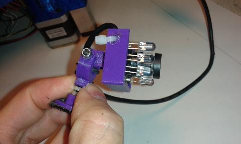
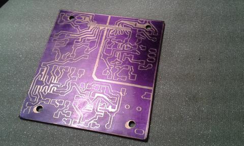
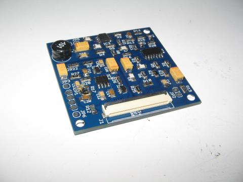
Más noticias: hemos probado la nueva PCB "profesional" del Pickup Driver y los resultados son ¡!fantásticos!!

El ruido eléctrico casi ha desaparecido y podemos enfocar con el diodo IR fácilmente y sin emborronar la película UV que era nuestro principal objetivo. También fuimos capaces de encender/apagar el diodo rojo, pero con algo de miedo por si lo destruíamos, así que además de la resistencia limitadora que pusimos, hemos limitado también la intensidad del diodo por firmware.

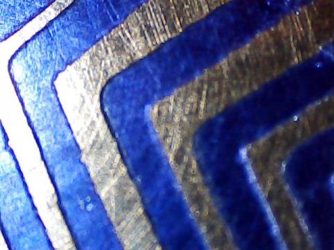
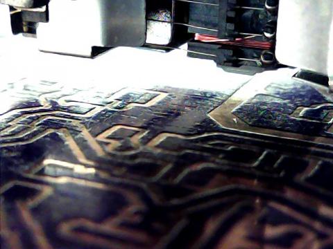
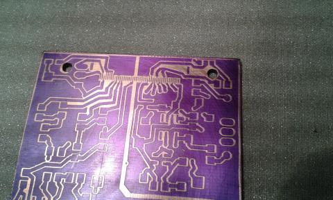
Echa un vistazo a las fotos que hemos tomado con un microscopio 20x. Corresponden a algunos detalles de la PCB del Pickup Driver.

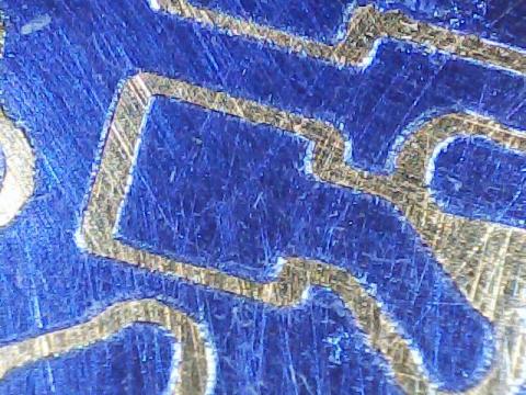
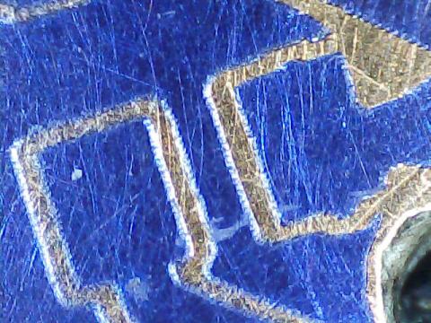
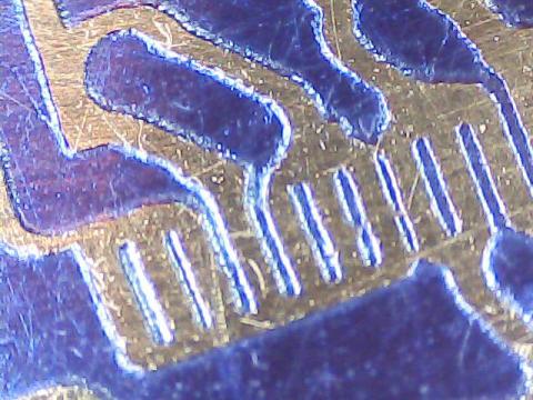
En esta última se puede apreciar las pistas del conector FPC (0.5mm de pitch). Es la cosa más pequeña que hemos impreso hasta ahora.

Seguiremos probando la calidad de impresión, pero podemos decir que esta etapa ha sido casi superada.

Próximas etapas: tenemos que imprimir en 3D algunas piezas que rediseñamos con mejoras y luego vamos a probar el proceso de "mini-fabricación" de una PCB de doble cara, incluyendo: diseño, fotograbado, taladrado de vias y agujeros, grabado en acido y  también dispensar pasta de soldar en los pads SMD. Al mismo tiempo comprobaremos la facilidad de uso y funcionamiento del software. Ya probamos el cabezal de impresión 3D, pero tal vez también lo probaremos un poco más. También nos gustaría probar a fresar/tallar materiales blandos como el poliestireno expandido o la cera. Puede ser útil para hacer moldes de silicona, por ejemplo.

Esperamos que si todo va bien la funcionalidad de la mini-fábrica de PCBs será la siguiente:

  • Fotograbar con láser  – consiste en dibujar el circuito de  la PCB en una  película sensible o PCB preparada para ello mediante un láser UV o IR.
  • Taladrar – permite la perforación de vias y agujeros usando cualquier mini-herramienta tipo Dremmel o Proxxon.
  • Fresar/Tallar/Grabar – usando la misma herramienta, el robot puede también fresar, tallar  materiales blandos o grabar el circuito en el cobre de la PCB con una fresa en v.
  • Dispensar pasta de soldar – con un dispensador basado en una jeringa, puede depositar con precisión pasta de soldar sobre los pads SMD de la PCB.
  • Plotear – si prefieres este método, puede trazar el circuito con un rotulador permanente.
  • Imprimir en 3D – la mini-fábrica incluye también una impresora 3D del tipo FFD, así que puedes hacer mandos de potenciómetros, cajas, paneles, etc. con filamento PLA o ABS. También puede imprimir circuitos con filamento conductor o con en el futuro con filamento de grafeno!!.
  • Y mucho más... porque es extensible y puede utilizar cualquier otra herramienta que se pueda acoplar en ella.

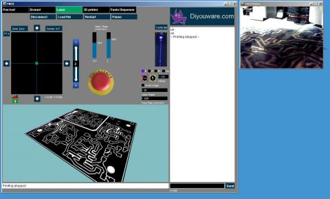
Toda esta funcionalidad está apoyada por un firmware especialmente adaptado a estas funciones y una nueva consola de gestión muy fácil de usar que hemos estado desarrollando durante este año. Ambos nos ayudarán a usar y controlar la mini- fábrica fácilmente.

También hemos detectado otras posibles aplicaciones:

  • Impresión 3D en resina UV – ya hemos hablado de esto en el blog. Es el conocido método de estereolitografía (SLA). Consiste en imprmir objetos 3D con un láser UV en resina foto-sensible. Tenemos ya algunos bocetos usando el pickup como fuente láser y probablemente será nuestro próximo proyecto.
  • Impresión 3D en bio-polímeros – consiste en imprimir en 3D sobre un bio-polímero para hacer ingeniería de tejidos. Parece fácil, je, je: sólo hay que añadir un foto-iniciador UV a un hidrogel e imprimir en 3D con el rayo láser. La ventaja de usar el Pickup está basada en la precisión debido a que el láser está perfectamente enfocado y muy cerca de la superficie del hidrogel. Hay laboratorios y universidades en todo el mundo trabajando ya en esto, pero de momento ninguna utiliza un Pickup.
  • Aplicaciones Microscópicas – no tenemos demasiado tiempo para más investigar en más áreas, pero soñamos con este tipo de proyectos. Consiste en usar el pickup como microscopio láser o para realizar unas pinzas moleculares. En teoría el rayo laser UV mide 0.5um de diámetro así que se podría realizar algo a dicha escala.

Finalmente nos comprometimos a publicar el documento del Dr. Futai. Aquí está:

http://www.digchip.com/datasheets/parts/datasheet/287/MLX75012.php

Es el manual de referencia del fotodiodo que creemos usa el pickup. Este documento nos confirma la funcionalidad de algunos de los pines que descubrimos el año pasado y nos descubre otros que no teníamos ni idea de ellos. También nos ha permitido tener un mejor control de los diodos láser del pickup.

Todavía hay un montón de funcionalidad por descubrir. Espero que nuestro proyecto haya inspirado a otras personas para investigar más pines y terminar nuestro trabajo. Para nosotros es suficiente de momento, ya que hemos cubierto nuestro objetivo, y vamos a seguir con nuestro proyecto real: la mini-fábrica de PCB.

Suena bien el nombre, ¿no?

  • Read more about Diyouware TwinTeeth: la mini-factoría de PCBs
  • Log in or register to post comments

Diyouware TwinTeeth: a PCB mini-factory

Submitted by DIYouware on Wed, 12/17/2014 - 10:30

Yes. We changed the name of the project to TwinTeeth. Why? Because we did not like MKII and also because that word inspired us in the robot designing. We don’t want to bore you now with the details so we will explain the full story when we will publish the project by january/february.

We have also coined a new term: PCB mini-factory. One year ago we had the vision of a robot which would help us to fabricate small PCB prototypes at home. During its development we though some possible definitions for this concept and now we think that mini-factory is the best.

More news: we tested the “professional-made” pickup’s driver PCB and the results are fantastic!!!

The electric noise has almost disappeared and we were able to focus with the IR diode very easily and without blurring the UV-film which was our primary goal. We were also able to turn on/off the red diode but we were a little afraid about destroying it, so in addition to the limiting resistor we also limited the diode intensity by firmware.

Take a look at some pics we took with a 20x microscope. They correspond to some details of the Pickup Driver PCB.

You can see on this one the 0.5mm pitch FPC connector tracks. It’s the small thing we have ever printed.

We will continue testing the printing quality but we can say that this stage has been almost surpassed.

Next stages: we have to 3D print some framework pieces we redesigned with improvements and then we will test the complete “mini-fabrication” process of a two-side PCB, including: designing, photoengraving, drilling, acid etching and dispensing solder paste on SMD pads. At the same time we will check usability and software functioning. We already tested the 3D printing toolhead but maybe we will also test it a little more. We would also like to test milling/carving on a soft material like expanded polystyrene or wax. For example it can be useful to make silicone moulds.

We hope the final functionality of the PCB mini-factory will be the following:

  • Laser photoengraving – consists in drawing the PCB circuit on sensitive film or board using a UV or IR laser.
  • Drilling – it allows drilling vias and holes using any mini-rotary tool like Dremel or Proxxon.
  • Milling/Carving/Etching – using the same tool, it can also mill or carve soft materials or etch PCB copper with a v-bit.
  • Solder paste dispensing – with a special syringe dispenser, it can deposit solder paste with precision on SMD PCBs pads.
  • Plotting – if you prefer this method, you can plot the circuit with a permanent pen-maker.
  • 3D printing – the mini-factory includes also a 3D printer so you can make knobs, boxes, front-panels, etc. with PLA or ABS. And also print circuits with conductive filament or graphene filament in the future!!
  • And much more… because it is extendable and you can use any other tool you can install on it.

All of this functionality is supported by the robot firmware and a new user-friendly management console we have been developing this year. It will help all of us to control the mini-factory and the different tools.

We also have detected some new possible applications:

  • UV resin 3D printing – we already talked about that. It is the well known Stereolithography (SLA) method. It consists in 3D printing objects with an UV laser in photo-sensible resin. We already drafted some blue-prints using the optical pickup and probably will be our next project.
  • Bio-polymer 3D printing – consists in 3D printing in  bio-polymers for tissue engineering. It seems easy: just add a UV photo-initiator to any hydro gel and 3D print on it with the UV laser beam. The benefit to use the pickup could be the precision because the laser beam is perfectly focused and close to the hydro gel surface. There are labs and universities around the world working on that.
  • Microscopic applications – we don’t have too much time to research more areas, but we dream with this kind of projects. It consists in using the pickup as a laser microscope or molecular tweezers.  In theory the laser beam is 0.5um wide so maybe is possible to do something at this scale.

Finally we promised to publish Dr. Futai’s document. Here it is:

http://www.digchip.com/datasheets/parts/datasheet/287/MLX75012.php

It is the datasheet of the photodiode array which we believe the pickup uses. This document confirms us the functionality of some of the pins we discovered last year and others we didn’t have any idea about it. It also allowed us to have a better control of the pickup’s laser diodes.

There is a lot of undiscovered pickup functionality yet. I hope our project had inspired some people to research more pins and end our job. For us it is enough as we covered our goals and we will continue with our real project: the PCB mini-factory.

Sounds good, isn't it?

  • Read more about Diyouware TwinTeeth: a PCB mini-factory
  • Log in or register to post comments

PCB soldada

Submitted by DIYouware on Tue, 12/09/2014 - 10:09

PCB soldered

El fin de semana pasado encontramos tiempo para soldar la PCB. Fue fácil pero tuvimos dificultades para encontrar una resistencia de 60 ohmios que se usa para limitar la corriente de los diodos rojo/IR. No hay mucho sitio así que buscando en algunos circuitos de chatarra electrónica finalmente encontramos una similar en un viejo televisor. No es SMD pero la hemos usado de todas formas hasta que recibamos una buena.


No tuvimos tiempo de probar el circuito. Quizás el fin de semana que viene


  • Read more about PCB soldada
  • Log in or register to post comments

PCB Soldered

Submitted by DIYouware on Tue, 12/09/2014 - 10:07

PCB soldered

Last weekend we found time to solder the PCB. It was easy but we had difficulties to find a 60 ohms SMD resistor to limit Red/IR diode current. We searched in some e-waste circuits and finally we found one similar in an old TV but not SMD. Anyway we provisionally used it till we receive the good one.

We did not have time to test it, maybe next weekend.


  • Read more about PCB Soldered
  • 1 comment
  • Log in or register to post comments

Pages

  • « first
  • ‹ previous
  • …
  • 7
  • 8
  • 9
  • 10
  • 11
  • 12
  • 13
  • 14
  • 15
  • …
  • next ›
  • last »

(c) 2013 Diyouware.com