Skip to main content area
Home
  • English
  • Español
  • Get it
  • Build it
  • Use it
  • Blog
  • DiyouPCB
    • Get It
    • Build
    • Use
    • Improve
    • Gallery
    • Downloads
  • Contact
  • About us

Llegaron las PCBs

Submitted by DIYouware on Fri, 11/28/2014 - 11:40

Hoy nos han llegado las muestras de PCB que pedimos a fábrica. Tienen un aspecto profesional. En cuanto podamos vamos a soldar una y a probarla.

Pedimos algunas PCBs a fabrica porque queríamos comprobar que el circuito funcionaba bien reduciendo el grosor de las pistas, separaciones, diámetro de las vías y dimensionamiento en general. La calidad de los prototipos que podemos hacer en casa, incluso con el robot, está lejos de la que podemos obtener con estos servicios profesionales. Pero como el circuito es muy sensible al ruido eléctrico queríamos comprobar si funcionaba mejor haciéndolo más compacto.


Esta PCB está basada en la versión más reciente del controlador del circuito...

  • Read more about Llegaron las PCBs
  • Log in or register to post comments

PCB arrived

Submitted by DIYouware on Fri, 11/28/2014 - 11:22

The PCB samples we ordered have arrived today. They have a professional look. We will build one and test it as soon as possible.

We ordered some PCBs to a professional manufacturer because we wanted to test if the circuit still works while reducing traces, clearances, vias and sizing. Usually the quality of this kind of services is far away from the quality we can obtain at home, even with the robot. But as the circuit is so sensible to electric noise we wanted to know if it works better in a proffesional way.

This PCB is based on the latest driver circuit version....

  • Read more about PCB arrived
  • Log in or register to post comments

Buenas noticias

Submitted by DIYouware on Thu, 11/20/2014 - 10:18

Tenemos buenas noticias.

La semana pasada el doctor Noboyuki Futai nos envió desde japón un documento que contiene la última información que necesitábamos para revelar todos los secretos del PHR-803T. Publicaremos el documento en los próximos días en la página de descargas junto con la última versión de la electrónica del DiyouDriver. Esta nueva versión no utiliza toda la información proporcionada por el documento. Lo hemos leído y revisado y creemos que la funcionalidad de la electrónica es suficiente para nuestro proyecto actual, pero el documento ha resuelto todas nuestras dudas, confirmó nuestras investigaciones y también permitirá que otras personas puedan explotar todas las capacidades del Pickup. Desde aquí nos gustaría expresar el Dr. Futai nuestro profundo agradecimiento por su importante contribución.

Por otro lado estamos esperando la llegada de algunas PCB profesionales que hemos pedido a fábrica. Estas PCBs son más pequeñas y compactas que las que hemos hecho por nosotros mismos pero tardan varias semanas en fabricarse y llegar a nuestras manos. En cuando lleguen probaremos una para ver si todo funciona y luego publicaremos los esquemas y el documento del Dr. Futai.

Mientras esperamos las PCBs estamos investigando otras áreas....

  • Read more about Buenas noticias
  • Log in or register to post comments

Good news

Submitted by DIYouware on Thu, 11/20/2014 - 10:12

We have very good news.

Last week Dr. Noboyuki Futai from Japan sent us a datasheet containing the last information we needed to reveal all the secrets of the PHR-803T. We will publish the document in the following days on the download page with the last version of the DiyouDriver’s schematics. This new version doesn’t use all the information provided by the document. We reviewed it and we think our electronics is enough for our current project, but the document solved all of our doubts, confirmed our researches and also will allow other people to exploit more capabilities of the pickup. From here we would like to express Dr. Futai our deep gratitude for his important contribution to the project.

On the other hand we are waiting for the arrival of some professional PCBs we ordered from a fab. These PCBs are smaller and more compact than those we made by ourselves but they take several weeks to come to our hands. As soon at they arrive we will test one to see if everything works fine and then we will publish the schematics and the document of Dr. Futai.

While waiting for the PCBs we are researching other areas.....

  • Read more about Good news
  • Log in or register to post comments

El Diodo Infrarrojo y el Dispensador de Pasta

Submitted by DIYouware on Tue, 11/11/2014 - 11:03

Estábamos a punto de tirar la toalla con el tema de enfocar con el diodo rojo cuando se nos ocurrió probar con el infrarrojo. Tenemos unos cuantos pickups con el diodo rojo quemado, pero los diodos infrarrojos parece que siguen vivos. Cuando descubrimos la forma de encender los diodos azul y rojo, también vimos que podíamos encender el infrarrojo (bueno realmente no lo vimos ya que la luz infrarroja es invisible al ojo humano pero se puede ver a través de cualquier cámara de vídeo) pero por alguna razón no obteníamos ninguna onda en la señal FE cuando intentábamos enfocar con él.

Revisando manuales antiguos de CD/DVD vimos que el fotodiodo normalmente está divido en dos patrones uno para DVD y otro para CD lo que nos hizo pensar que algún pin del pickup tenía que tener la función de cambiar de un array de fotodiodos a otro. Y así fue: hay un pin que permite cambiar del modo Blu-ray/DVD al modo CD y si no se utiliza con el diodo infrarrojo, éste se enciende, pero no se obtiene señal al enfocar.

Hemos cambiado ligeramente el circuito y ahora somos capaces de enfocar también con el diodo infrarrojo y la buena noticia es que limitando la corriente con una resistencia parece que no se auto-destruye. Todavía tenemos que probar más pero tiene buena pinta.

Por otro lado hemos diseñado y construido el cabezal para dispensar pasta de soldar. La idea es que el robot automatice también esta tarea.

Hemos utilizado un pequeño motor de pasos, un eje lineal con una varilla roscada y una jeringa que contiene la pasta. Hace unas semanas diseñamos también el programa ULP para Eagle Cadsoft que nos permite generar el g-code para depositar la pasta....

  • Read more about El Diodo Infrarrojo y el Dispensador de Pasta
  • Log in or register to post comments

The Infrared Diode and the Paste Dispenser

Submitted by DIYouware on Tue, 11/11/2014 - 10:51

We were almost to throw in the towel trying to focus with the red diode when we did a quick test with the infrared one. We have a few pickups with the red diode burned but the infrared diodes seem still alive. When we discovered the way to turn on/off the blue and red pickup’s diodes we were also able to manage the infrared one (The infrared light is invisible to the human eye but you can see it through any video camera). But for some reason we didn’t see any wave in FE signal when trying to focus with it.

Reviewing old CD/DVD player’s manuals we saw that the photodiode is usually divided into two patterns: one for DVD and another for CD. That made us think that some pickup pin had to have the function of change from one photodiode pattern to the other. And so it was. There is a pin which allows switch from Blu-ray/DVD to CD mode. If not used, infrared diode turns on but no wave is obtained while focusing. We slightly modified the driver circuit and now we are able to focus with the infrared diode. The good news is that limiting the current with a resistor it seems it doesn't destroy itself. We still need to test a little more but it looks promising.

On the other hand, last week we designed and built the solder paste dispenser toolhead. The idea is that the robot also automates this task.

We used a small stepper motor, a linear axis, a small leadscrew and a syringe containing the solder paste. A few weeks ago we developed also the Eagle Cadsoft’s ULP program which generates the g-code file to move the robot and deposit the paste in the component's pads....

  • Read more about The Infrared Diode and the Paste Dispenser
  • Log in or register to post comments

Apostando al rojo o al negro

Submitted by DIYouware on Thu, 10/30/2014 - 10:05

Hemos soldado y probado el nuevo circuito del laser y la buena noticia es que funciona bien incluso mejor que el prototipo de la MKI. El aislamiento de los circuitos analógicos y digitales genera ahora una señal FE libre de ruido que nos permite enfocar mejor y con más precisión que en versiones anteriores. Analizando la señal con el osciloscopio vimos que casi no hay ningún ruido, sólo un pequeño ruido de fondo de RF probablemente generado por el medio ambiente.

La mala noticia es que desafortunadamente no pudimos enfocar con el láser rojo.

  • Read more about Apostando al rojo o al negro
  • Log in or register to post comments

Betting on red or black

Submitted by DIYouware on Thu, 10/30/2014 - 10:02

We made and tested the new laser circuit driver and the good news is that it works fine even better than MKI prototype. The isolation of the analog and digital circuits produces a free-of-noise FE signal which allow us to focus really better and which more accuracy than in previous versions. Analyzing the signal with the oscilloscope we saw that we don’t almost have any noise, only a small background RF noise probably generated by the environment.

The bad news is that unfortunally we could not focus with the red laser.

  • Read more about Betting on red or black
  • Log in or register to post comments

Vecindario Ruidoso

Submitted by DIYouware on Thu, 10/23/2014 - 13:05

Seguimos luchando con el ruido eléctrico. Como dijimos en anteriores entradas del blog este problema esta afectando a la señal de enfoque.

Estamos utilizando la electrónica del PHR-803T y el método astigmático para enfocar el láser en la PCB. Para obtener la “S-Curve” calculamos y amplificamos las señales A, B, C, D obtenidas del fotodiodo del pickup y generamos con ellas una señal analógica (FE o Focus Error) que leemos desde un puerto del Arduino. De forma similar los reproductores de DVD o Blu-Ray enfocan el rayo láser en la superficie del disco, pero utilizando circuitos más complejos, ya que tienen que hacerlo en tiempo real según la música o la película se están ejecutando. En nuestro caso sólo enfocamos el rayo láser cuando empezamos a imprimir la PCB así que nuestro circuito es más sencillo.

Hemos desarrollado todo este método y la electrónica necesaria el año pasado, y estaba funcionando muy bien en la MKI, pero en la MKII cometimos el error de mezclar los circuitos analógicos y digitales en la misma placa. Así que los circuitos digitales inducen ruido en las señales analógicas que son muy sensibles y eclipsan la “S-Curve”.

Creemos que la solución pasa por aislar los circuitos analógicos y digitales en diferentes áreas de la PCB y usar diferentes líneas de GND y VCC conectadas en una configuración en estrella a un punto común. También reducir al mínimo las pistas por las que viaja el PWM, aislar los pines de los conectores y desacoplar todo con algunos condensadores de tantalo que son más adecuados para la gama de frecuencias que estamos tratando. También hemos incluimos un choke por si filtra algo las frecuencias ruidosas de la fuente de alimentación.

Hemos rediseñamos el circuito y la PCB, y aquí está: (cortesía de ZofzPCB 3D Gerber viewer)


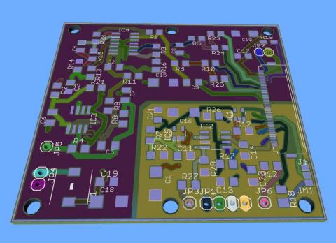
El área más pequeña es el circuito digital: el “vecindario ruidoso”

  • Read more about Vecindario Ruidoso
  • Log in or register to post comments

Noisy Neighbourhood

Submitted by DIYouware on Thu, 10/23/2014 - 12:39

We are still fighting with the electric noise. As we said in previous blog entries this problem affects the focus signal.

We are using the PHR-803T electronics and the astigmatic method to focus de laser on the PCB. To obtain the S-Curve we calc and amplify the A,B,C,D signals obtained from the pickup’s photodiode array and generate an analog signal (FE or Focus Error) which we read from an Arduino port. In a similar way DVD or Blu-Ray players focus the laser beam on the disc surface but using more complex circuitry because they have to do it in real time as the music or movie is playing. We only focus the laser beam once when begin to print the PCB so our circuit is more simple.

We developed all this method and electronics last year and were working fine in MKI, but in MKII we did the mistake to mix the digital and analog circuitry on the same PCB, so the digital circuitry induce noise on the sensible analog signals and eclipsed the S-Curve.

We think the solution will be to isolated digital and analog circuits on different PCB areas and use different GND and VCC lines connected in a star configuration to a common point. Also to reduce PWM traces length ad minimum, isolate connector pins and decouple everything with some tantalum capacitors which are more suitable to the range of frequencies we are treating. We also included a choke to see if it filter well the power suply noisy frecuencies.

So we redesigned the circuit and the board and here it is: (courtesy of ZofzPCB 3D Gerber viewer)


The smaller area is the digital circuit: the noisy neighbourhood.

  • Read more about Noisy Neighbourhood
  • Log in or register to post comments

Pages

  • « first
  • ‹ previous
  • …
  • 8
  • 9
  • 10
  • 11
  • 12
  • 13
  • 14
  • 15
  • 16
  • …
  • next ›
  • last »

(c) 2013 Diyouware.com